Wifi joystick with display

User avatar
HermannSW
Posts: 97
Joined: Fri Oct 27, 2017 6:58 am
Location: Eberbach, Germany
Contact:

Wifi joystick with display

Postby HermannSW » Fri Mar 20, 2020 2:03 pm

I am just building a fast caterpillar robot (raspcatbot):
https://www.raspberrypi.org/forums/view ... 7&t=267999

Even when it will drive autonomously, it needs a wireless heartbeat signal from wireless device.
Either on command or when heartbeat got missed, the robot will do immediate emergency stop (because it runs up to 5m/s or 18km/h).

I want to have a wireless joystick as well for initial driving tests with that robot.
Using an ESP32 with builtin SSD1306 OLED is ideal:
  • has analog inputs, so can deal with joystick
  • has Wifi to send heartbeat and/or joystick data to robot
  • has display for
    1. joystick data
    2. status information from robot
This is initial sketch just displaying joystick data, no Wifi and other stuff:

Code: Select all

#include <Wire.h>
#include "SSD1306Wire.h"

SSD1306Wire display(0x3c, 5, 4);

void draw(String &s) {
  display.clear();
  display.drawStringMaxWidth(0, 0, 128, s);
  display.display();
}

void setup() {
  display.init();
  display.flipScreenVertically();
  display.setTextAlignment(TEXT_ALIGN_LEFT);
  display.setFont(ArialMT_Plain_16);
}

void loop() {
  draw(String(map(analogRead(15),0,4095,0,255))+" : "+String(map(analogRead(13),0,4095,0,255))+" : "+String(analogRead(12)==0));
  delay(100);
}

With joystick screwed to ESP32 board with OLED, and (380mA) lipo for powering via GND/5V:
Image


The two 12V/1500rpm caterpillar motors get (over)powered by diy 3S+1S=4S lipo with 16.8V (original T101 motors are 12V/330rpm only).
Robot gets controlled by onboard (after assembling) Raspberry Pi3A+ (quad core, camera, Wifi, ...).
In this photo last night Pi3A+ did run robot motor at maximal speed (pwm=255).
Measured speed was 1600rpm (26rps!), or 5m/s (18km/h) with wheel diameter of 60mm (measured with laser tachometer):
Image
Last edited by HermannSW on Fri Mar 20, 2020 2:11 pm, edited 2 times in total.

User avatar
HermannSW
Posts: 97
Joined: Fri Oct 27, 2017 6:58 am
Location: Eberbach, Germany
Contact:

Re: Wifi joystick with display

Postby HermannSW » Sun Mar 22, 2020 7:48 pm

After a series of raspcatbot functional testing now the caterpillar motors do not disturb the camera tilt servo anymore (after I provided a separate power source for the servo):
https://www.raspberrypi.org/forums/view ... 5#p1630185
Image

Because of that I wanted to control the robot with the Wifi joystick.
I learned how to use WifiMulti.h to connect to my home Wifi, and send small TCP packets to the robot's Raspberry Pi3A+.
The Pi just received data with "netcat" command, but that allowed to measure that <0.5ms are needed for transfer:
https://twitter.com/HermannSW/status/12 ... 0157451268

Next I combined the joystick sketch from previous posting and the TCP code. To my surprise the joystick code stopped working after executing "WiFiMulti.run()". Search with DuckDuckGo found the explantion:
https://esp32.com/viewtopic.php?f=19&t= ... 972a8e6f81

Only ADC1 pins can be used at the same time as WiFi, and with my (Wemos) ESP32 with Oled those pins are only GPIO36 and GPIO39 (available ADC pins GPIO25 and GPIO26 are not mentioned in the posting, but do not work with Wifi). For some reason joystick switch (pressing on the black knob) does only work with analogRead(), and for that an ADC1 pin is missing on my board. I gave up and superglued a red button onto the left side of the module. Only for the demo its value is displayed, later it will trigger robot emergency stop by stop sending heartbeat signals to the Pi, and the Pi does reads with timeouts and triggers emergency stop on a missed heartbeat:
Image

This youtube video shows Wifi joystick as well as Pi3A+ ssh session output together:
https://www.youtube.com/watch?v=MONsPmT ... e=youtu.be

This is new sketch used, later I will use client.write() instead of client.print() and send 2-byte messages consisting of both joystick coordinates:

Code: Select all

#include <Wire.h>
#include "SSD1306Wire.h"

SSD1306Wire display(0x3c, 5, 4);

#include "WiFi.h"
#include <WiFiMulti.h>

WiFiMulti WiFiMulti;
WiFiClient client;

const char * ssid = "FRITZ!Box 6490 Cable";
const char * password = "verySecret";

void draw(const String &s) {
  display.clear();
  display.drawStringMaxWidth(0, 0, 128, s);
  display.display();
}

void setup() {
  display.init();
  display.flipScreenVertically();
  display.setTextAlignment(TEXT_ALIGN_LEFT);
  display.setFont(ArialMT_Plain_16);

  delay(10);

  WiFiMulti.addAP(ssid, password);

  String line="Waiting for WiFi... ";
  draw(line);

  while(WiFiMulti.run() != WL_CONNECTED) {
    line += ".";
    draw(line);
    delay(500);
  }

  draw(String(WiFi.localIP()));

  delay(500);

  const uint16_t port = 1337;
  const char * host = "192.168.178.163";

  draw("Connecting to "+String(host)+":"+String(port));

  if (!client.connect(host, port)) {
    draw("Connection failed.");
    for(;;) {}
  }
    
  draw("connected"); 
  delay(1000); 
}

void loop() {
  String s=String(map(analogRead(39),0,4095,0,255))+" : "+String(map(analogRead(36),0,4095,0,255))+" : "+String(digitalRead(16));
  draw(s);
  client.print(s+"\n");
  delay(500);
}

User avatar
HermannSW
Posts: 97
Joined: Fri Oct 27, 2017 6:58 am
Location: Eberbach, Germany
Contact:

Re: Wifi joystick with display

Postby HermannSW » Mon Mar 23, 2020 11:19 pm

I was able to control raspicatbot's motors for the 1st time with Wifi joystick.
Unfortunately I had to comment out the lines handling the timeouts.
Reason was that after a short time the timeouts triggered, although I did set timeout to 1s!
I will need to debug that.

The red button of Wifi joystick needs to be pressed the whole time as dead-man button.

This is main loop of ESP32 sketch:

Code: Select all

...
void loop() {
  if (digitalRead(16) == 0)
  {
    draw("emergency stop triggered");
    for(;;)  {}
  }

  unsigned char buf[2] = {
    map(analogRead(36),0,4095,0,255),
    map(analogRead(39),0,4095,0,255)
  };
  
  client.write(buf, 2);
  draw(String(buf[0])+" : "+String(buf[1]));
  
  delay(5);
}
And this is working loop on Raspberry Pi3A+:

Code: Select all

  while (1)
  {
    fprintf(stderr, ".");
//    if (select(0 + 1, &set, NULL, NULL, &timeout) <= 0)  emergency_stop(1);
    if (read(0, buf, 1 ) < 1)  emergency_stop(2);
//    if (select(0 + 1, &set, NULL, NULL, &timeout) <= 0)  emergency_stop(3);
    if (read(0, buf+1, 1 ) < 1)  emergency_stop(4);

    gpioWrite(gpioLeftFwd, buf[0] >= 128);
    gpioWrite(gpioLeftRew, buf[0] < 128);
    gpioWrite(gpioRghtFwd, buf[0] >= 128);
    gpioWrite(gpioRghtRew, buf[0] < 128);
    gpioPWM(gpioLeftPwm, (buf[0] < 128) ? 255-2*buf[0] : 2*buf[0]-255);
    gpioPWM(gpioRghtPwm, (buf[0] < 128) ? 255-2*buf[0] : 2*buf[0]-255);
  }
Code on Pi3A+ is started this way:

Code: Select all

pi@raspberrypi3Aplus:~/raspcatbot $ nc -l 1337 | sudo ./dead-man_button 
.........................
I recorded a video of test, it shows that jacking up needs improvement:
https://www.youtube.com/watch?v=UiOidcK ... e=youtu.be
Image

User avatar
HermannSW
Posts: 97
Joined: Fri Oct 27, 2017 6:58 am
Location: Eberbach, Germany
Contact:

Re: Wifi joystick with display

Postby HermannSW » Tue Mar 24, 2020 9:25 pm

I found the reason for timeout not working yesterday, details in this posting:
https://www.raspberrypi.org/forums/view ... 9#p1631419

I did select only minimal speeds with the Wifi joystick, and even with that the robot already moves so fast!
Seeing that, 5m/s on the ground sounds reasonable, a real 1.2kg power robot

https://www.youtube.com/watch?v=vJfdLPI ... e=youtu.be
Image

User avatar
HermannSW
Posts: 97
Joined: Fri Oct 27, 2017 6:58 am
Location: Eberbach, Germany
Contact:

Re: Wifi joystick with display

Postby HermannSW » Sat Mar 28, 2020 3:26 pm

Previous raspcatbot was just too fast for reliable joystick control.
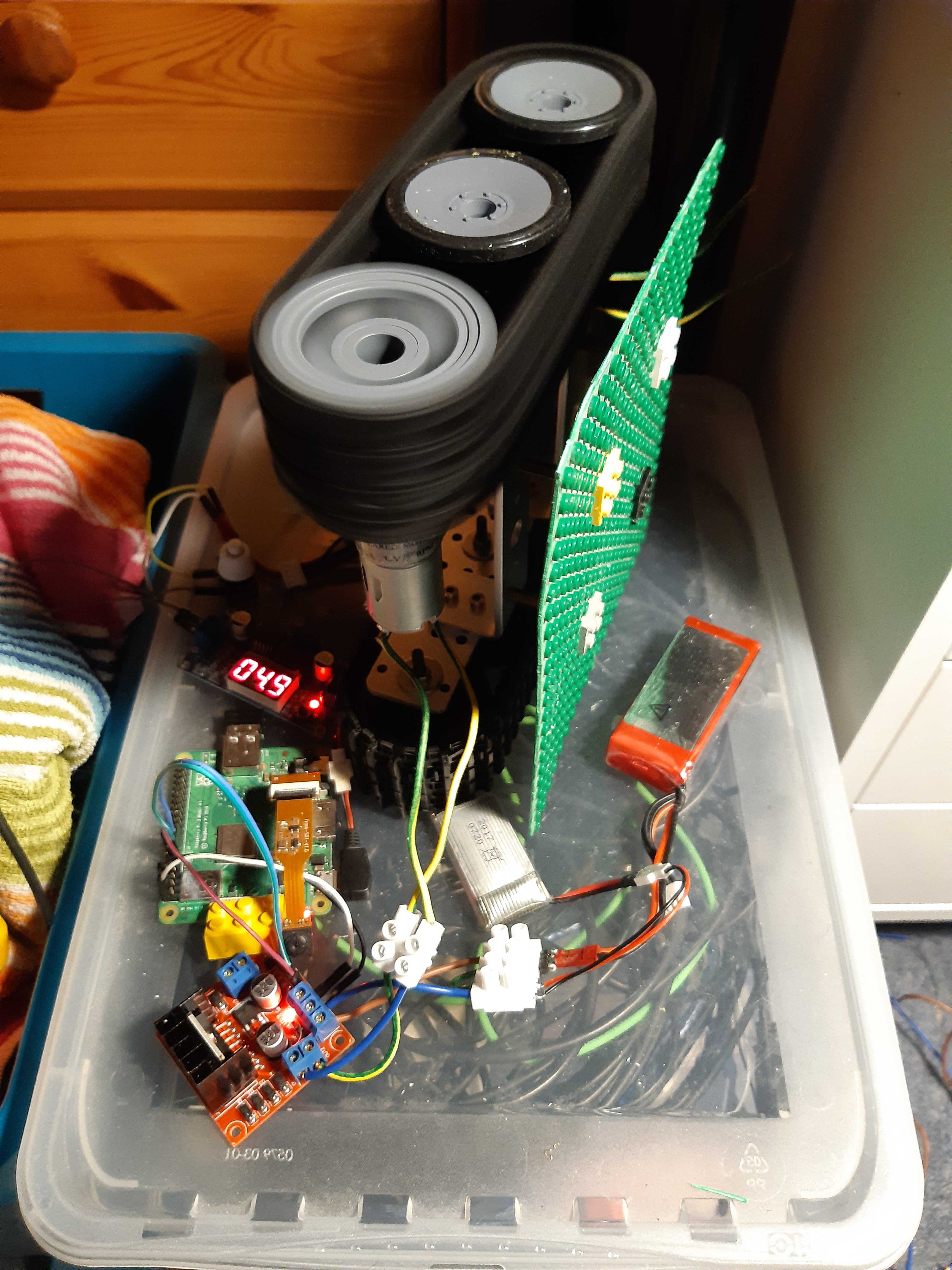
So I replaced the 1500rpm gear motors with original 330rpm motors on my 2nd T101 platform.
The new design with just one lipo is much smaller, until now 3S 1000mAh 25C lipo.
But ordered 4S 1300mAh 95C lipos just arrived ;-)
Image


I want the robot to be able to drive outside, so I had to get rid of home router dependency.
While it was easy to make the ESP32 an AP, it is not easy to determine the devices only connected to it.
Making the Raspberry Pi (ZeroW now) AP is not that easy either.
So I took the easiest solution and made my Android smartphone the access point.
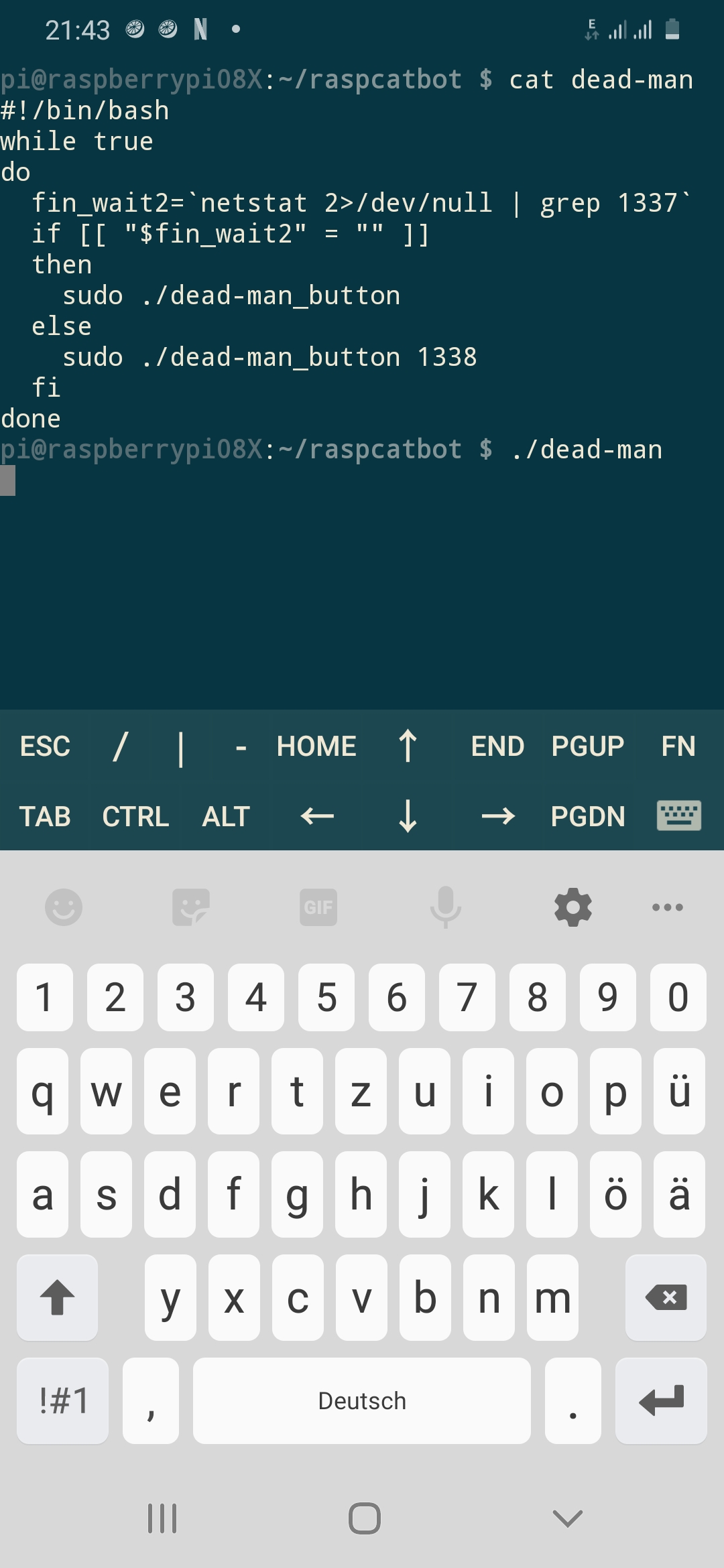
Pi program dead-man_button.c needs to be started, no problem using JuiceSSH app on the smartphone.
Even changes to C code and compilation can be done that way, even when outside:
Image


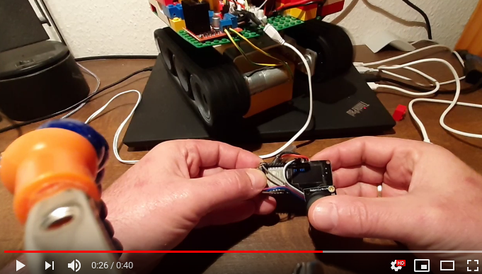
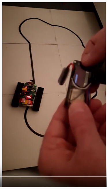
I did record a first video with now fully functional Wifi joystick on target ground, hardplates I already used for preparation of another robot (Asuro) for 2007 Vienna RobotChallenge. Plates and courses for different challenges can be found here (google translated from German):
https://stamm-wilbrandt.de/RobotChallenge/
Image


This is the new Wifi joystick raspcatbot video:
https://www.youtube.com/watch?v=sqHJmhtsR-M
Image


And here is the code, in order to be prepared for corrections/enhancements as gists.

This is Pi dead-man_button.c (no need for netcat anymore, TCP server code now included):
https://gist.github.com/Hermann-SW/b489 ... 10c8d00ae7

This is dead-man helper code. Sometimes an emergency stop caused by heartbeat loss does not correctly cleanup. Then port 1337 is blocked for 1 minute in FIN_WAIT2 state. This helper code starts dead-man_button on port 1318 in that case:
https://gist.github.com/Hermann-SW/042b ... 22fe2a8d5f

Code: Select all

#!/bin/bash
while true
do
  fin_wait2=`netstat 2>/dev/null | grep 1337`
  if [[ "$fin_wait2" = "" ]]
  then
    sudo ./dead-man_button
  else
    sudo ./dead-man_button 1338
  fi
done
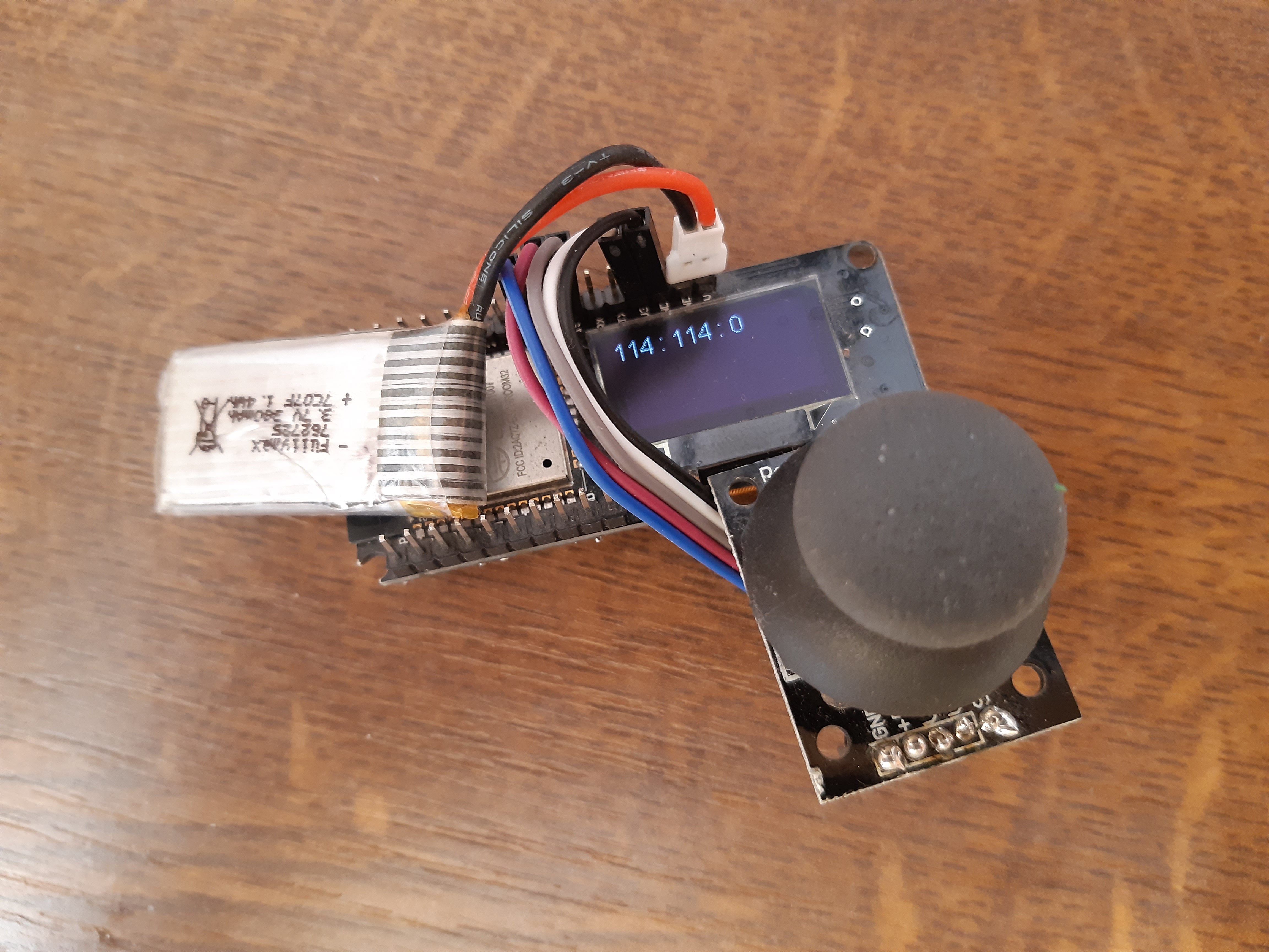
Finally this is wifi_joystick.ino sketch. Now connects to either 1337 or 1338 port. Split for forward/backward is now done at 112 (the joystick default position value). I had no idea how to use two axis of joystick to control two motors of caterpillar robot. Did try the easiest thing, and that was a good choice. Control one motor by one axis, the other motor by the other. Both axis maximal is full speed forward, both axix 0 is full speed backward. one axis 255 and the other 0 is full speed center point rotation (clockwise or anticlockwise). And you can use any setting else, so small changes in direction can be easily done. Anyway it is not that easy to control the robot with it as you can see in the video, I hope it will get better with more handson:
https://gist.github.com/Hermann-SW/afeb ... 57e7048f87

Code: Select all

...
while (1)
  {
//    fprintf(stderr, ".");
    struct timeval timeout1={.tv_sec=0, .tv_usec=500000};
    if (select(nfd + 1, &set, NULL, NULL, &timeout1) <= 0)  emergency_stop(1);
    if (read(nfd, buf, 1 ) < 1)  emergency_stop(2);
    struct timeval timeout2={.tv_sec=0, .tv_usec=500000};
    if (select(nfd + 1, &set, NULL, NULL, &timeout2) <= 0)  emergency_stop(3);
    if (read(nfd, buf+4, 1 ) < 1)  emergency_stop(4);  

    gpioWrite(gpioLeftFwd, buf[4] >= 112);
    gpioWrite(gpioLeftRew, buf[4] < 112);
    gpioWrite(gpioRghtFwd, buf[0] >= 112);
    gpioWrite(gpioRghtRew, buf[0] < 112);
    gpioPWM(gpioLeftPwm, (buf[4] < 112) ? 255-(255/112.0)*buf[4] : (255/143.0)*buf[4]-255);
    gpioPWM(gpioRghtPwm, (buf[0] < 112) ? 255-(255/112.0)*buf[0] : (255/143.0)*buf[0]-255);
  }
  ...

Who is online

Users browsing this forum: PCRiscV and 91 guests