Page 1 of 1

Pin change interrupt multiple fire

Posted: Tue Nov 14, 2017 2:07 pm
by snail71
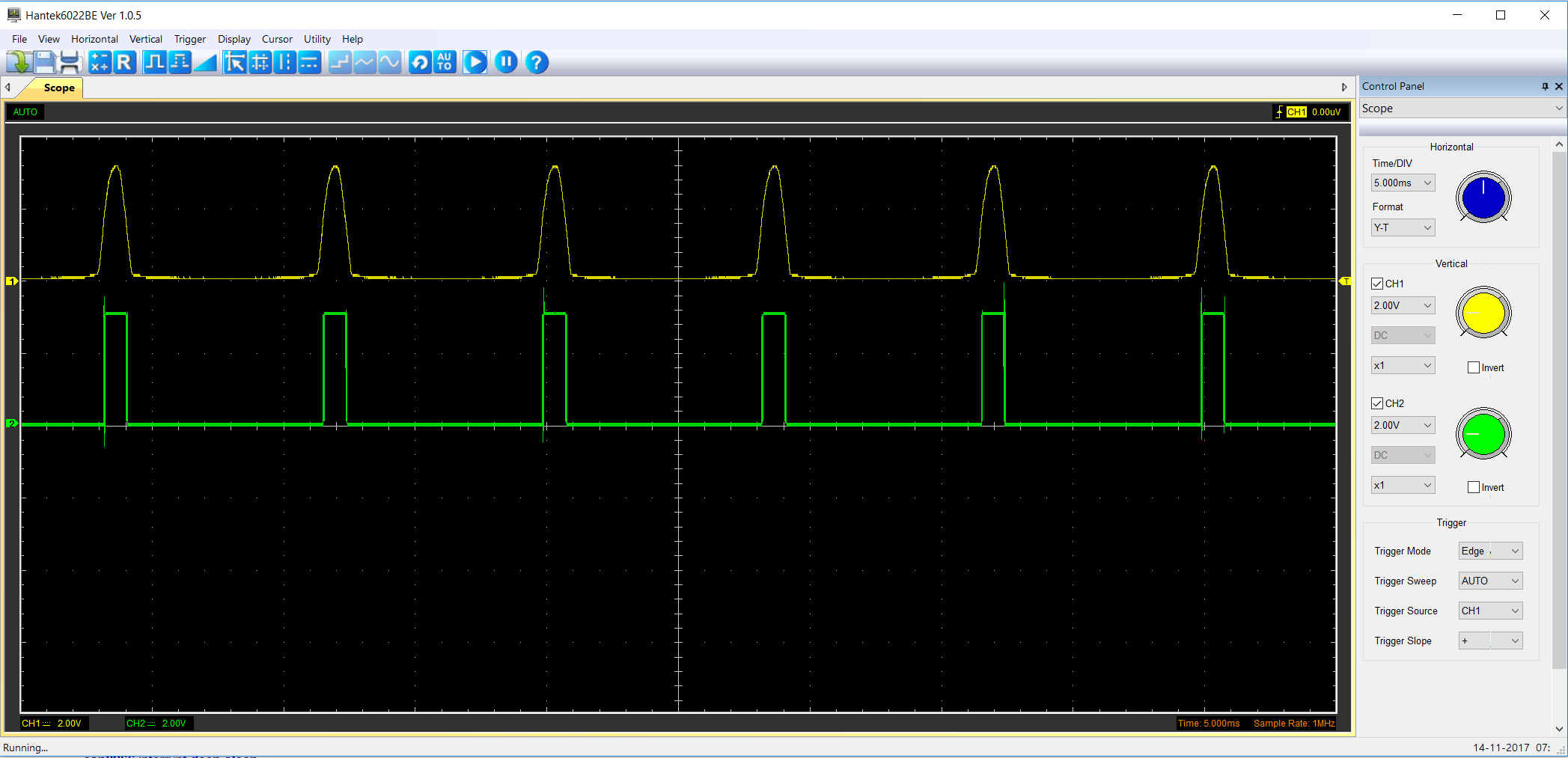
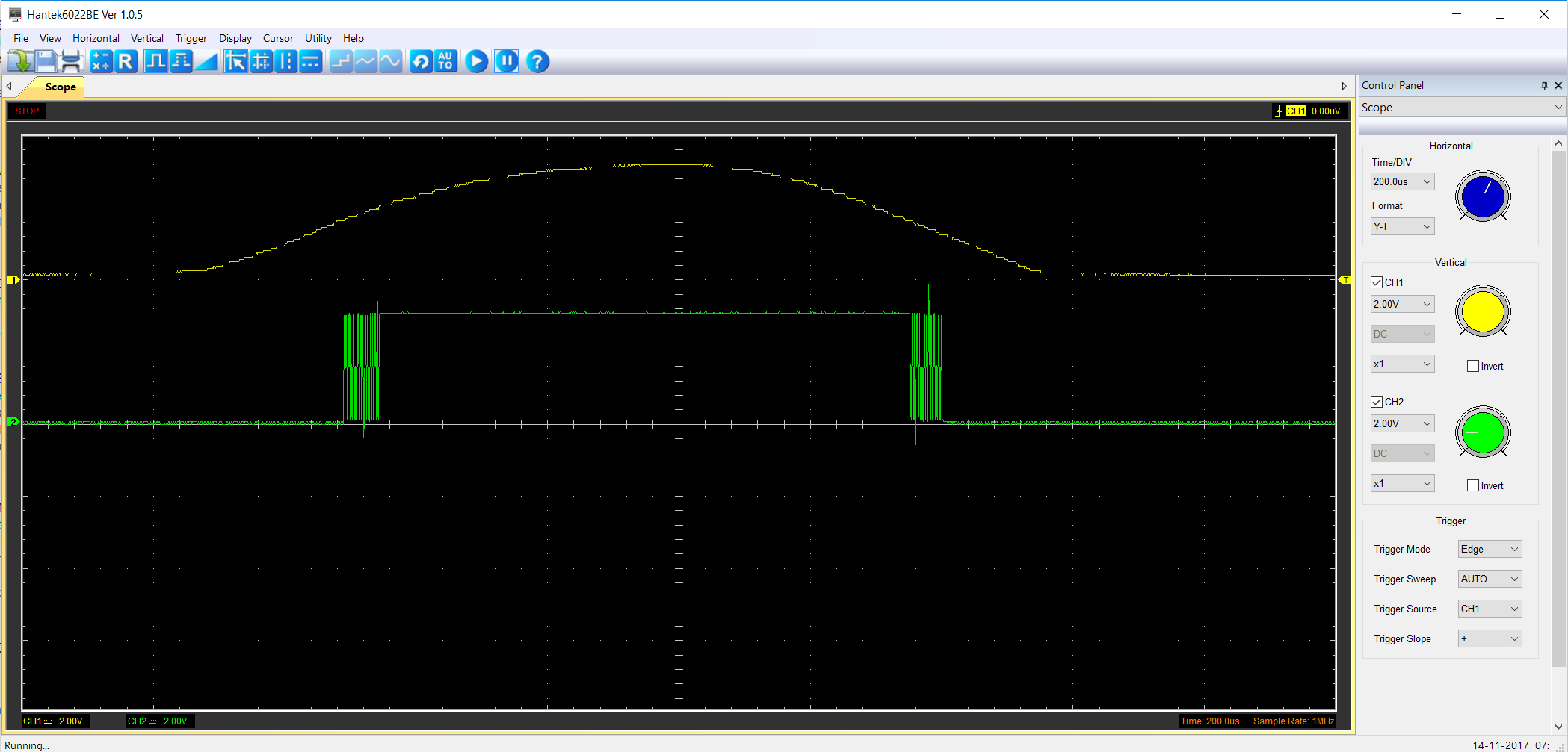
I have a pin (34) setup as an input. This pin is connected to a triac opto that generates a clean signal. I have it setup to generate an interrupt on falling edge. This is so I can detect zero crossings that will be used to fire an output triac. The problem I am having is that with each pulse the interrupt is firing MANY times on both rising and falling edges. It is acting like it is seeing bounces from a mechanical switch not from a clean sign wave signal.

Image

Image

Here is some of the code:

#define ZX_PIN 34
#define TRIAC1 26

void zero_cross()
{
// just toggle the pin for now
digitalWrite(TRIAC1,!digitalRead(TRIAC1);
}

void setup()
{
pinMode(ZX_PIN,INPUT);
pinMode(TRIAC1,OUTPUT);
digitalWrite(TRIAC1,LOW);
attachInterrupt(digitalPinToInterrupt(ZX_PIN),zero_cross,FALLING);
}

void loop()
{

}

Re: Pin change interrupt multiple fire

Posted: Mon Feb 19, 2018 1:38 am
by jgustavoam
Hi,
Please specify wich pulses are in the Scope screen .
Are Upper pulses from output of opto coupler ?
And lower pulses ?

Re: Pin change interrupt multiple fire

Posted: Mon Feb 19, 2018 7:24 pm
by OttoES
I had a similar problem on the ESP32. (If you really want a clean signal I think that you will need an external Schmitt trigger.)

I solved it differently with a timer as follows:

Code: Select all

static uint32_t prevT = 0;

void IRAM_ATTR IOhandleInterrupt()
{
   uint32_t  t = micros();
   uint32_t dt          = t -prevT;
   if (dt<150) return;
   prevT       = t;
   ..... your code
}
   

Re: Pin change interrupt multiple fire

Posted: Tue Feb 20, 2018 10:17 pm
by mickeypop
NOTE the green wave in your 2nd scope picture.
In each tower it is switching on and off at half the tower height.
Not having your schematic, this leads me to think you are not at true GND with ref. to zero crossing or there is a wrong scope setting.

NOTE the spikes on both the leading and trailing edges of the pulses.
This looks like your load has both Capacitive and Inductive features to it.

OttoES suggestion of an external Schmitt trigger is probably a good idea however if your Zero Crossing is not true this may not work by itself.

A simple software work around is easy;
- In the ISR
  • 1 Detach the ISR
    2 Take a time snapshot ISR_var = millis();
    3 Store ISR_FIRED = true;
    4 Process the rest of the isr
In main loop, an if(ISR_FIRED) checks when proper time has passed to re attach ISR and sets ISR_FIRED = false;

Code: Select all

if( ISR_FIRED )
{
    if( ( millis() - ISR_var) >= SomePreSerTimeVar  )
     {
          re-attach irq
          ISR_FIRED = false;
     }
}
This simple way stops the ISR from bouncing and waits a safe time to re-attach.

You only need to decide the time length to detach the ISR.

You probably need a time just wider than a normal pulse.

For the time shots; Remember Arduino can read milli seconds as well as micro seconds according to your circuit needs.

== Hope it Helps ==